Making a light detection circuit is possible using Light Dependent Resistors (LDRs) with a microcontroller like Arduino. This lesson shows how to do so using the simple concept of voltage dividers.
List of Content
1. Needed Components
- Arduino Uno
- LDR (Light Dependent Resistor)
- 10kΩ Resistor
- 330Ω Resistor
- LED
- Breadboard
- Jumper Wires
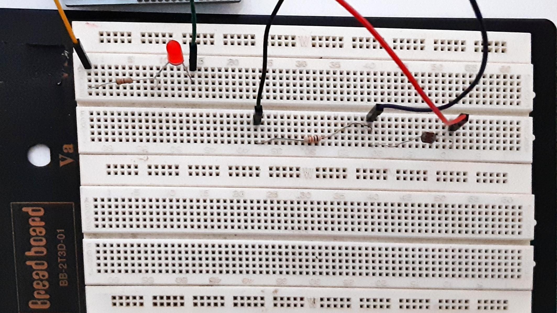
2. Connections and Schematics


- LDR Voltage Divider Circuit:
- Connect LDR to 5V and analog pin A0.
- Connect 10kΩ resistor between A0 and GND.
- LED:
- Connect anode to digital pin 9 (with 330Ω resistor).
- Cathode to GND.
3. How LDRs Work & Voltage Divider
- LDR Principle: A Light dependent Resistor has a resistance that decreases or increases depending on the amount of light it is exposed to. For the LDR in this example, resistance decreases with increasing light intensity.
- Since the resistance is what changes, we cannot get a measurement directly to Arduino, because Arduino can only measure and get electrical input (voltage), not resistance. Solution? A voltage divider circuit.
4. Voltage Dividers
Voltage Divider: Convert changes in resistance into voltage changes.
The output voltage (Vout) in a voltage divider circuit is calculated using:
Vout = (R2 / (R1 + R2)) × Vcc
Where:
- Vout = Output voltage (measured at the junction between R1 and R2)
- R1 = Resistance of the first component (LDR in this case)
- R2 = Fixed resistor value (10kΩ in our circuit)
- Vcc = Supply voltage (5V from Arduino)
How it works with an LDR:
As light increases → LDR resistance (R1) decreases → Vout increases
As light decreases → LDR resistance (R1) increases → Vout decreases
Here, LDR acts as R1 (variable resistance).
5. Code
const int ldrPin = A0;
const int ledPin = 9;
int threshold = 500; // Adjust based on ambient light

void setup() {
  pinMode(ledPin, OUTPUT);
  Serial.begin(9600);
}

void loop() {
  int ldrValue = analogRead(ldrPin);
  Serial.print("LDR Value: ");
  Serial.println(ldrValue);

  if (ldrValue < threshold) {
    digitalWrite(ledPin, HIGH); // Turn LED on in darkness
  } else {
    digitalWrite(ledPin, LOW);
  }
  delay(100);
}
6. Notes and Advanced Tips
- While experimenting, you may want to make sure the LED light doesn’t reach the LDR (otherwise it may give a false light signal and close up the LED)
- Try to add potentiometer to adjust threshold dynamically. You should use analogRead() with a large resistor in series to the potentiometer.
- Create sunrise/sunset simulator with PWM, using analogWrite().
Now that you learned how to use LDR, you can expand even further by integrating more sensors or adding better functionality.
Leave a Reply