Using LM35 with Arduino allows you to measure the temperature through an analog sensor, and use it to react accordingly. This lesson covers some of the basics you will need while using LM35 analog temperature sensor.
1. Needed Components
- Arduino Board (Arduino Uno or another type)
- LM35 Temperature Sensor
- LED (any color)
- Resistor (330 ohm)
- Breadboard
- Jumper Wires
- Power Supply (USB cable or battery pack)
2. Connecting Your Circuit
Set Up the Breadboard:
- LM35 Sensor Connections:
- LED Connections:
- Connect the anode (longer leg) of the LED to digital pin 13 on the Arduino.
- Connect the cathode (shorter leg) of the LED to a 330-ohm resistor, and connect the other end of the resistor to the GND on the Arduino.
- Connect VCC pin of the LM35 to the 5V pin on the Arduino
- GND pin of the LM35 –> GND pin on the Arduino.
- Vout pin of the LM35 –> analog pin A0 on the Arduino.
Schematics and Pictures
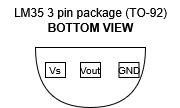
- MAKE SURE TO CONNECT THE LM35 SENSOR’S PINS PROPERLY. Otherwise LM35 will heat and may get damaged as shown below.
- Put the sensor’s legs towards your face and its flat part towards the roof, then follow the below diagran to identify the pins (for TO-92 package)
- Circuit Diagram

3. How the LM35 Sensor Works
The LM35 is a precision analog temperature sensor that provides an output voltage linearly proportional to the Celsius temperature. Here’s how it works:
- The LM35 outputs 10 mV per degree Celsius. For example:
- At 25°C, the output voltage is 250 mV.
- At 30°C, the output voltage is 300 mV.
- The output voltage is read by the Arduino’s analog input pin (A0).
- The Arduino converts the analog voltage to a digital value using the analogRead() function.
- The digital value is converted to temperature using the formula:
Temperature (°C) = (Analog Value × 5.0) / 1024.0 × 100LM35 Package Types:
- TO-92: The most common package, looks like a small transistor. Easy to use on a breadboard.
- TO-220: Larger package, often used for higher power applications.
- SOIC: Surface-mount package, used in compact designs.
Where to Get the LM35:
- You can purchase the LM35 from electronics component stores like:
- Online retailers
- Local electronics shops: Check for availability in your area.
4. The Code and How It Works
Here’s the Arduino code to blink an LED when the temperature exceeds a certain threshold:
// Define pin numbers
const int lm35Pin = A0;  // LM35 connected to analog pin A0
const int ledPin = 13;   // LED connected to digital pin 13

// Define temperature threshold
const float tempThreshold = 30.0; // Blink LED if temperature > 30°C

void setup() {
  // Set pin modes
  pinMode(lm35Pin, INPUT);
  pinMode(ledPin, OUTPUT);

  // Initialize serial communication
  Serial.begin(9600);
}

void loop() {
  // Read the analog value from the LM35
  int analogValue = analogRead(lm35Pin);

  // Convert the analog value to temperature in Celsius
  float temperature = (analogValue * 5.0) / 1024.0 * 100;

  // Print temperature to Serial Monitor
  Serial.print("Temperature: ");
  Serial.print(temperature);
  Serial.println(" °C");

  // Control LED based on temperature
  if (temperature > tempThreshold) {
    digitalWrite(ledPin, HIGH); // Turn on LED
    delay(500);                 // Blink delay
    digitalWrite(ledPin, LOW);  // Turn off LED
    delay(500);                 // Blink delay
  } else {
    digitalWrite(ledPin, LOW);  // Turn off LED
  }

  // Add a small delay for stability
  delay(100);
}
How This Code Works:
- Variable Declaration:
lm35Pinis set toA0for the LM35 sensor.ledPinis set to13for the LED.tempThresholdis set to30.0(the temperature threshold in Celsius).
- Setup:
- The
pinMode()function sets thelm35Pinas an input and theledPinas an output. - Serial communication is initialized for debugging.
- Loop:
- The
analogRead()function reads the analog value from the LM35 sensor. - The analog value is converted to temperature using the formula.
- The temperature is printed to the Serial Monitor.
- The if condition checks if the temperature is greater than the threshold (
tempThreshold):- If true, the LED blinks by turning on and off with a 500 ms delay.
- If false, the LED remains off.
- Delay:
- A small delay is added for stability and to avoid rapid readings.
5. How to Go Further in Your Temperature-Controlled LED Circuit
- Adjust Temperature Threshold: Change the
tempThresholdvalue in the code to trigger the LED at a different temperature. - Add a Buzzer: Include a buzzer to sound an alarm when the temperature exceeds the threshold.
- Multiple LEDs: Use multiple LEDs to indicate different temperature ranges (e.g., Green for normal, Yellow for warning, Red for high).
- LCD Display: Add an LCD or OLED display to show the temperature in real-time.
- Cooling Fan: Integrate a small DC motor or fan to activate when the temperature is too high.
- Data Logging: Use an SD card module to log temperature data over time.
- Wireless Communication: Add a Bluetooth or Wi-Fi module to send temperature data to a smartphone or computer.
- Advanced Logic: Implement hysteresis to prevent rapid toggling of the LED near the threshold.
This project demonstrates how to use the LM35 temperature sensor to create a temperature-controlled LED system. Experiment with the code and hardware to explore more advanced applications!
Leave a Reply