On this page:
- List of components
- Connections: Traffic light circuit schematics
- The code and how it works
- How to go further in your traffic light circuit
In the previous lesson, we had learned about making a single traffic light circuit and use Arduino to control it. This lesson expands the circuit to build a crossroad traffic lights with Arduino, using either additional pins or a simple trick.
1. Needed Components
- Arduino Board (Arduino Uno or another type)
- LEDs (2 Red, 2 Green)
- Resistors (330 Ohm for the LEDS, 10K Ohm for the button)
- Breadboard
- Jumper Wires
- Push Button
- Power Supply (USB cable or battery pack)
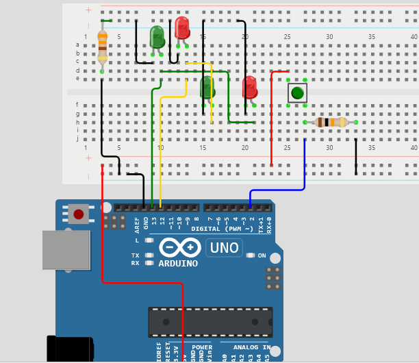
2. Connecting Your Traffic Light Circuit
- Set Up the Breadboard:
- Place the LEDs on the breadboard. The longer leg (anode) is the positive side, and the shorter leg (cathode) is the negative side.
- Connect the anode of the first traffic light’s LEDs to a digital pin on the Arduino (e.g., Red to pin 12, Green to pin 13).
- Connect the anode of the other traffic lights LEDs to the anode of the opposite color (i.e., red with green, green to red).
- Connect one leg of the 330-ohm resistor to the cathode of each LED, and connect the other leg of the resistor to the ground (GND) on the Arduino.
- Connect one corner of the push button to 5V on Arduino
- Connect the opposite corner of the push button to a pin (pin no 2) and a large 10K Ohm resistor.
- Connect the other leg of the 10K Ohm resistor to ground (GND)
- Schematics and Pictures

3. Code
Here’s a simple Arduino code for the traffic light system:
// Define pin numbers
const int greenPedPin = 12;
const int greenCarPin = 13;
const int buttonPin=2;

//Create variable for button signal
int buttonSignal=0;
void setup() {
  // Set pin modes
  pinMode(greenPedPin, OUTPUT);
  pinMode(greenCarPin, OUTPUT);
  pinMode(buttonPin, INPUT);
}

void loop() {
 //read buttonPin and store it to buttonSignal variable
  buttonSignal=digitalRead(buttonPin);
//Go for Cars, Stop for Pedestrian
  digitalWrite(greenPedPin, LOW);
  digitalWrite(greenCarPin, HIGH);

  if(buttonSignal){
  delay(3000);
//Go for pedestrian, Stop for cars
  digitalWrite(greenCarPin, LOW);
  digitalWrite(greenPedPin, HIGH); // Red for 5 seconds
  delay(5000); // Green for 5 seconds
  }
}
How the traffic code works with Arduino
Variable declaration
at the beginning, we stored the numbers (12,13 and 2) into variables (greenPedPin, greenCarPin, buttonPin).
GreenPedPin controls green light for pedestrians and red light for cars.
GreenCarPin controls green light for cars and red light for pedestrians.
We also created a variable (buttonSignal) for storing the signal coming from the button.
Setup
The pinMode() Command determines the type of pin (input or output) and therefore its function and internal connections.
Loop
We first read the buttonPin and store the value into buttonSignal.
Next, we used digitalWrite() to turn the cars’ green light and pedestrian red lights on (HIGH) or off (LOW).
The if Command checks if the button is pressed (if buttonSignal equals 1). Based on that, it flips the condition for some time, which will remain until the loop returns to start.
4. Advanced Tips for Modification
- Smart Traffic Lights: In the next lesson, we will expand the project to control the intersection traffic light with a sensor instead of a button.
- Timing Adjustments: Modify the delay times for each light to simulate different traffic conditions
- 2nd Press Timer: The time you wait when the button hasn’t been pressed for a long time shouldn’t be the same with that when the button is continuously pressed (sometimes we can’t stop the cars every few seconds for pedestrians). Use a timer to check for last press time.
This project can be as simple or complex as you want, depending on your interests and skills. Enjoy building your crossroad traffic light system with Arduino! You can also use digital logic circuits or other simple Integrated Circuits (ICs) to do the samr project. Stay tuned to our lessons for more information and lessons.
Leave a Reply