
After learning how to make a basic traffic light and a crossroad traffic light with pedestrian button, we will replace the button in this lesson using the HC-SR04 ultrasonic distance sensor with Arduino to control our traffic light.
List of Content
- List of Components
- Connections: HC-SR04 and Traffic Light Circuit Schematics
- How the HC-SR04 Sensor Works
- The Code and How It Works
- How to Go Further in Your Traffic Light Circuit with Sensor Integration
1. Needed Components
- Arduino Board (Arduino Uno or another type)
- HC-SR04 Ultrasonic Sensor
- LEDs (Red, Green)
- Resistors (330 ohm for each LED)
- Breadboard
- Jumper Wires
- Power Supply (USB cable or battery pack)
2. Connecting Your Circuit
Set Up the Breadboard:
- HC-SR04 Sensor Connections:
- Connect the VCC pin of the HC-SR04 to the 5V pin on the Arduino.
- GND pin of the HC-SR04 –> GND pin on the Arduino.
- Trig pin of the HC-SR04 –> digital pin 10 on the Arduino.
- Echo pin of the HC-SR04 –> digital pin 9 on the Arduino.
- Traffic Light LEDs:
- Connect the anode (longer leg) of the Red LED to digital pin 12 on the Arduino.
- Anode of the Green LED –> digital pin 13 on the Arduino.
- Cathode (shorter leg) of each LED –> 330-ohm resistor, and connect the other end of the resistor to the GND on the Arduino.
Schematics and Pictures

3. How the HC-SR04 Sensor Works
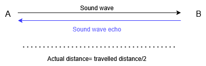
The HC-SR04 ultrasonic sensor measures distance using sound waves. Here’s how it works:
- The Trig pin sends out a high-frequency sound wave (ultrasound).
- The sound wave travels through the air and bounces off an object.
- The Echo pin detects the reflected sound wave.

- The time taken for the sound wave to travel to the object and back is used to calculate the distance using the formula:
Distance = (Travel Time × Speed of Sound) / 2
- The speed of sound is approximately 343 meters per second (or 0.0343 cm/µs).
- The time is measured in microseconds (µs).
4. The Code and How It Works
Here’s the Arduino code to control the traffic light’s green/red status based on the distance measured by the HC-SR04 sensor:
// Define pin numbers
const int trigPin = 10;    // HC-SR04 Trigger pin
const int echoPin = 9;   // HC-SR04 Echo pin
const int redPin = 12;    // Red LED pin
const int greenPin = 13;  // Green LED pin

void setup() {
  // Initialize serial communication
  Serial.begin(9600);

  // Set pin modes
  pinMode(trigPin, OUTPUT);
  pinMode(echoPin, INPUT);
  pinMode(redPin, OUTPUT);
  pinMode(greenPin, OUTPUT);
}

void loop() {
  // Measure distance using the HC-SR04 sensor
  long duration, distance;
  digitalWrite(trigPin, LOW);
  delayMicroseconds(2);
  digitalWrite(trigPin, HIGH);
  delayMicroseconds(10);
  digitalWrite(trigPin, LOW);

  // Read the echo pin and calculate distance
  duration = pulseIn(echoPin, HIGH);
  distance = duration * 0.0343 / 2; // Distance in cm

  // Print distance to Serial Monitor
  Serial.print("Distance: ");
  Serial.print(distance);
  Serial.println(" cm");

  // Control traffic light based on distance
  if (distance < 20) { // If object is within 20 cm
    digitalWrite(redPin, HIGH);   // Turn on Red LED
    digitalWrite(greenPin, LOW);  // Turn off Green LED
  } else {
    digitalWrite(redPin, LOW);    // Turn off Red LED
    digitalWrite(greenPin, HIGH); // Turn on Green LED
  }

  // Add a small delay for stability
  delay(100);
}
How This Code Works:
- Variable Declaration: trigPin, echoPin for the HC-SR04 sensor and greenPin and redPin for the LEDs are defined.
- Setup:
- Serial communication is initialized so we can print the distance (to check/debug).
- Pin modes are set (Trig as output, Echo as input, LEDs as output).
- Loop:
- According the the HC-SR04 datasheet, we need to turn trigPin for 10 microseconds to make it send a sound wave burst
- Immediately after the waves are sent and their echo return to the sensor, the echoPin return a HIGH (5V) pulse for a period equal to the elapsed travel time. We get this time in µs using pulseIn() function
- Distance is calculated using the formula and printed to the Serial Monitor.
- If an object is within 20 cm, the Red LED turns on, and the Green LED turns off.
- If no object is detected within 20 cm, the Green LED turns on, and the Red LED turns off.
- A small delay is added for stability.
5. How to Go Further in Your Traffic Light Circuit with Sensor Integration
- Adjust Detection Range: Modify the distance threshold in the code (e.g.,
if (distance < 50)) to change when the traffic light reacts. - Add a Yellow LED: Include a Yellow LED to simulate a warning state when an object is approaching the detection range.
- Multiple Sensors: Use multiple HC-SR04 sensors to detect objects from different directions and control multiple traffic lights.
- Traffic Light Timing: Add a delay before and after switching from Red to Green (inside the if loop) to simulate real-world traffic light behavior.
- Pedestrian Crossing: Integrate a push button to allow pedestrians to override the sensor and stop traffic.
- Display Distance: Use an LCD or OLED display to show the measured distance in real-time.
- Advanced Logic: Implement more complex logic, such as prioritizing certain directions or adjusting light timing based on traffic density.
Now that you tried to make an ultrasonic distance sensor based traffic light control system, experiment with the code and hardware to explore more possibilities! Stay tuned to Samerli lessons and keep on going if you would like to learn more. All the best in your learning journey.
Leave a Reply