One of the first things you can start doing with Arduino after learning how to light an LED and blink it is to make a traffic light project with Arduino. This lesson goes through the basic steps using two different connection methods.
List of content
1. Needed Components
- Arduino Board (Arduino Uno or another type)
- LEDs (Red, Green)
- Resistors (330 ohm for each LED)
- Breadboard
- Jumper Wires
- Power Supply (USB cable or battery pack)
2. Connecting Your Traffic Light Circuit
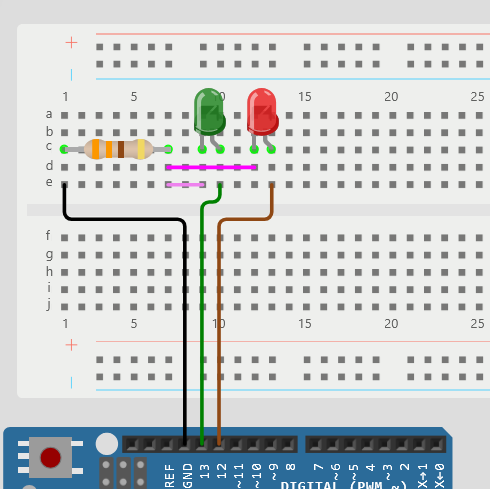
- Set Up the Breadboard:
- Place the LEDs on the breadboard. The longer leg (anode) is the positive side, and the shorter leg (cathode) is the negative side.
- Connect the anode of each LED to a digital pin on the Arduino (e.g., Red to pin 12, Green to pin 13).
- Connect one leg of the 330-ohm resistor to the cathode of each LED, and connect the other leg of the resistor to the ground (GND) on the Arduino.
- Schematics and Pictures


3. Code
Here’s a simple Arduino code for the traffic light system:
// Define pin numbers
const int redPin = 12;
const int greenPin = 13;

void setup() {
  // Set pin modes
  pinMode(redPin, OUTPUT);
  pinMode(greenPin, OUTPUT);
}

void loop() {
  // Red light
  digitalWrite(redPin, HIGH);
  delay(5000); // Red for 5 seconds
  digitalWrite(redPin, LOW);

  // Green light
  digitalWrite(greenPin, HIGH);
  delay(5000); // Green for 5 seconds
  digitalWrite(greenPin, LOW);
}
How this code words:
Variable declaration
at the beginning, we stored the numbers 12 and 13 into variables (redPin, GreenPin)
Setup
The pinMode() Command determines the type of pin (input or output) and therefore its function and internal connections.
Loop
The digitalWrite() Command turns a pin on (HIGH) or off (LOW). The delay() Command pauses the program from running according to the milliseconds number given.
4. Advanced Tips for Modification
- Multiple Traffic Lights: In the next lesson, we will expand the project to control multiple sets of traffic lights for intersections.
- Pedestrian Crossing: Add a push button to allow pedestrians to request a crossing. When pressed, the traffic light can switch to red, and a buzzer can sound to indicate it’s safe to cross.
- Timing Adjustments: Modify the delay times for each light to simulate different traffic conditions (e.g., rush hour vs. off-peak).
- Traffic Sensors: Integrate infrared or ultrasonic sensors to detect vehicles and adjust the light timing based on traffic flow.
- LED Matrix Display: Use an LED matrix to display additional information, such as countdown timers for each light.
- Remote Control: Implement a remote control feature using an IR remote to manually change the lights or override the automatic sequence.
- Mobile App Control: Use Bluetooth or Wi-Fi modules (like HC-05 or ESP8266) to control the traffic lights via a mobile app.
This project can be as simple or complex as you want, depending on your interests and skills. Enjoy building your traffic light system!
Leave a Reply