In this lesson, we will learn the very basics of using Arduino by making a simple blinking LED project with Arduino.
List of Content
1. Needed Components
- Arduino Board (Arduino Uno or another type)
- LED (any color)
- Resistor (330 ohm)
- Breadboard
- Jumper Wires
- Power Supply (USB cable or battery pack)
2. Connecting Your Blinking LED Circuit
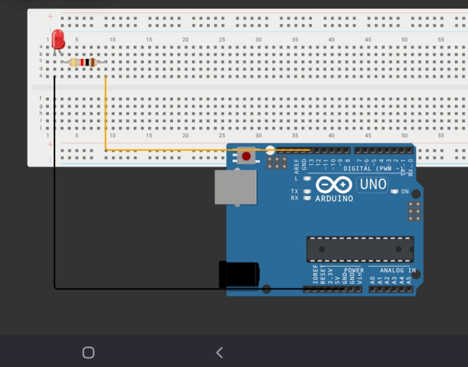
Set Up the Breadboard:
- Place the LED on the breadboard. The longer leg (anode) is the positive side, and the shorter leg (cathode) is the negative side.
- Connect the cathode of the LED to a digital pin on the Arduino (e.g., pin 13).
- Connect one leg of the 330-ohm resistor to the anode of the LED, and connect the other leg of the resistor to the ground (GND) on the Arduino.
Schematics and Pictures

Alternative connection:
- You can connect the LED’s anode to pin 13, and its cathode to a grounded resistor.

3. Code
In order to upload any code to your Arduino board, you can download and use the Arduino IDE here. Make sure you keep your internet connected for the first time after installing the IDE and give permission to all driver installations so you can upload. After the first time, you shouldn’t need the internet (unless you want to download code pieces called libraries).
After installing Arduino IDE, you can upload all your codes using the following steps:
- Connect Arduino to your PC through the USB connector (usually a blue wire)
- From the top bar (or tools on old versions) choose the board type you are using (Arduino Uno)
- Then choose the port (for example COM3). If your PC doesn’t have a USB port and you are using a USB to serial converter, you may find different options, choose the suitable one.
- After selecting everything, click the upload arrow (pointing right). Make sure you actually wrote code in the IDE, unless you want to upload an empty code to Arduino. You should upload every time you change you code.
As your first code, you can copy and paste the below code into Arduino IDE, a simple Arduino code to make the LED blink:
// Define pin number
const int ledPin = 13; // LED connected to digital pin 13

void setup() {
  // Set pin mode
  pinMode(ledPin, OUTPUT); // Set the LED pin as an output
}

void loop() {
  // Turn the LED on
  digitalWrite(ledPin, HIGH); // Send HIGH signal to turn on the LED
  delay(1000); // Wait for 1 second (1000 milliseconds)

  // Turn the LED off
  digitalWrite(ledPin, LOW); // Send LOW signal to turn off the LED
  delay(1000); // Wait for 1 second
}
How This Code Works:
- Variable Declaration: At the beginning, we store the number
13into the variableledPinto represent the pin where the LED is connected. - Setup: The
pinMode()function sets theledPinas an output pin, meaning it will send signals to the LED. - Loop:
- The
digitalWrite()function turns the LED on by sending aHIGHsignal and off by sending aLOWsignal. - The
delay()function pauses the program for a specified time (in milliseconds). Here, it pauses for 1 second between turning the LED on and off.
4. Tips for Modification
Now that you you know how to make a simple blinking LED project with Arduino, it may be a good idea to take the next step
- Change Blinking Speed: Modify the
delay()values to make the LED blink faster or slower.
- Example:
delay(500)for 0.5 seconds ordelay(2000)for 2 seconds.
- Multiple LEDs: Add more LEDs and control them independently by connecting them to different pins and modifying the code. When you are done, check our traffic light project.
- Patterns: Create custom blinking patterns, such as Morse code or alternating blinks between multiple LEDs.
- Brightness Control: Use PWM (Pulse Width Modulation) pins (marked with ~, pins 3, 5, 6, 9, 10, or 11 on Arduino Uno) and the
analogWrite()function to control the LED brightness. Ex: analogWrite(3,124) for halfing brightness. - External Input: Add a push button to control when the LED blinks, as in our lesson 3. For example, the LED only blinks when the button is pressed.
5. Frequently Asked Question (FAQs)
Why does my Arduino blink pin 13 even before I upload the code
Some Arduino boards come with the simplest blinking code uploaded
What does the resistor do?
The resistor protects the LED from getting too much current. In electronics, the amount of current (how fast electrons flow) depends on the pushing force (the voltage) and the resisting force (resistance).
The bigger the resistor, the slower the flow (less current).
Doesn’t the resistor have to be before the LED to protect it?
NO, the resistor can be AFTER or before the LED. As long as it is in series (on the same pipeline) with the LED, it can still protect it
This simple blinking LED project is a great starting point for learning Arduino. You can expand it in countless ways as you gain more experience! Enjoy experimenting!
Leave a Reply